Tutorial: Segmentation
This page has been archived and is no longer maintained. It describes an earlier generation of the Vesuvius Challenge pipeline — tools, data layouts, and results referenced here may have been superseded. See Open Problems for the current state of the pipeline and Prizes for what is open today.
Last updated: February 20, 2025
Table of Contents
Installation Instructions
Due to a complex set of dependencies, it is highly recommended to use the docker image. We host an up-to-date image on the github container registry which can be pulled with a simple command :
docker pull ghcr.io/scrollprize/villa/volume-cartographer:edge
If you want to install vc3d from source, the easiest path is to look at the Dockerfile (and the shared install_build_deps.sh it uses) and adapt for your environment. Building from source presently requires a *nix like environment for atomic rename support. If you are on Windows, either use the docker image or WSL.
installation instructions for docker
running docker as a non-root user
if you are using Ubuntu, the default open file limit is 1024. You may encounter errors when running VC3D. To fix this, run ulimit -Sn 750000 (or some other high number) in the terminal you plan to launch VC3D/Docker from before doing so.
Data formatting
VC3D requires a few changes to the data you may already have downloaded. All data must be in OME-Zarr format, of dtype uint8, and contain a meta.json file. To check if your zarr is in uint8 already, open a resolution group zarray file (located at /path/to.zarr/0/.zarray) look at the dtype field. "|u1" is uint8, and "|u2" is uint16.
The meta.json contains the following information. The only real change from a standard VC meta.json is the inclusion of the format:"zarr" key.
{"height":3550,"max":65535.0,"min":0.0,"name":"PHerc0332, 7.91 - zarr - s3_raw","slices":9778,"type":"vol","uuid":"20231117143551-zarr-s3_raw","voxelsize":7.91,"width":3400, "format":"zarr"}
Your folder structure should resemble this:
.
└── scroll1.volpkg/
    ├── volumes/
    │   ├── s1_uint8_ome.zarr -- this is your volume data/
    │   │   └── meta.json - REQUIRED!
    │   └── 050_entire_scroll1_ome.zarr -- this is your surface prediction/
    │       └── meta.json - REQUIRED!
    ├── paths
    ├── normal_grids - REQUIRED!
    └── config.json - REQUIRED!
There is only one additional requirement with the latest updates , which is the computation of a normal grid. These can be computed using the vc_gen_normalgrids tool , and should be placed at the root of your volpkg in a folder called normal_grids.
Scroll 5 (PHerc172) has precomputed versions of direction fields and normal grids, available at the following links:
- normal_grids
- fiber-directions
- the horizontal fiber field was only computed from z2000:z8000, the vertical covers the entire height
- structure-tensor-normal
Launching VC3D
If you're using docker :
xhost +local:docker
sudo docker run -it --rm \
  -v "/path/to/data/:/path/to/data/" \
  -v /tmp/.X11-unix:/tmp/.X11-unix \
  -e DISPLAY=$DISPLAY \
  -e QT_QPA_PLATFORM=xcb \
  -e QT_X11_NO_MITSHM=1 \
ghcr.io/scrollprize/villa/volume-cartographer:edge
From source :
/path/to/build/bin/VC3D
Navigation
First , click File -> Open volpkg and select the volpkg you wish to work with (select the folder ending in .volpkg)
On the left side of the UI, you have a few dock widgets. The first being the Volume Package / Surface List. The most important things to note here are the Volume dropdown list, which selects the currently displayed volume, and the paths surface list, which selects the currently displayed segment. Selecting a Surface ID should populate the Surface volume view in the top left, and initialize the rest the volume viewers.
Widgets
Most actions in VC3D are grouped into similar sets of actions controlled by a widget.
Volume Package
Main UI widget for interacting with the volume package and surface list
Reload Surfaces: checks for new segmentations in the currently selected directory (by default, this is{volpkg}/pathsFilters: Apply a single (or multiple) filters to show or hide specific surface ids from the current set- the most important one to remember here is
Current Segment Only, which will hide the intersection overlays of all other segmentations in the volume viewers (this can greatly speed up ui interaction)
- the most important one to remember here is
Approved,Defective,Reviewed,Revisit,Inspect: tags which can be applied to the surface meta.json , and filtered againstGenerate Surface MaskandAppend Surface Mask: Create a binary mask representing the valid surface, and optionally append the current selected volume to it as a multipage tif
Location
Main UI widget for adjusting the ROI and display of the volume viewers
Focus: Displays the current location of the focus point (in XYZ) -- also can be used to set the focus point by modifying the values in the text boxZoom: Can be used in place of scroll wheel based zooming , mostly exists to alleviate touchy track pad zoomingOverlay Volume: Selects the volume to overlay onto the base volumeOverlay opacity: Modifies the opacity of the overlay volumeAxis overlay opacity: Modifies the opacity of the plane slice axis overlaysOverlay threshold: The value of the overlay array below which will not be rendered on the base volume (useful for removing background)Overlay colormap: The colormap to use for the overlay volumeUse axis aligned slices: by default, vc3d attempts to align your XZ and YZ planes orthogonal to the normal of the current selected surface, this checkbox will instead use the plane normal as the axis to slice alongShow axis overlays in XY view: if you do not wish to view the axis overlays in the XY view, this checkbox will disable them
Keybinds:
Right mouse + drag: pans the current viewerScroll wheel: zooms the current viewerCtrl + left mouse button: centers the focus point on the cursor positionScroll wheel click + drag: rotates the slicing pane in the XZ or XY volume viewersSpacebar: toggles the overlay on / offC: toggle a composite view of the current surface in the segmentation window (parameters of which can be located in the "composite" dock tab, next to the location tab)
Segmentation
Primary entry point for interacting with the segmentation
Enable editing: Must be checked to enable any of the actions in this widget. Creates a copy of the base surface upon which we perform any of the following actionsSurface Growth- grouping of settings mostly pertaining to theGrowactionSteps: The number of "generations" the growth action will undertakeAllowed Directions: Limits the directions of growth relative to the flattened 2d quad surface! (i.e if you look in the segmentation window in the top left, and you set 'up' it will grow towards the top of the window)Limit Z range: Constrains the growth to a selectedZrangeVolume: the volume to pass to thetracer()call should be a surface prediction volume!
Editing- grouping of settings which mostly apply to drag/push/pull actions for mesh deformation. All mesh deformation-type actions are performed on a gaussian-like area which has a circular shape centered at the current mouse location and whose strength is reduced as we reach the edges. Radius is in quad vertices in the 2d flattened surface.Max Radius: the maximum radius of the area to be affected by the actionSigma: the strength of the push/pull on affected vertices other the original one (aka how quickly the influence tapers as we step away from the original point)Push Pull Step: The number of "offset steps" to take along the surface normal (in voxels) for each push/pull action (this parameter only affects the push/pull in the segmentation window that is applied withFandG)
Direction FieldsZarr folder: the path containing the direction field you want to use for optimization (ex:/path/to/scroll.volpkg/fiber-directions.zarr/horizontal) these are optionalOrientation: the orientation/type of the direction field (from horizontal, vertical, or normal)Scale level: the zarr resolution from which these were computedWeight: the weight to apply to the field when optimizing.
Corrections: group which controls / manages the "correction points" for the current growth sessionNew correction set: creates a new point collection containing a single "correction"
Keybinds:
ForG: push/pull the current surface in a positive or negative direction along the surface normal (only works in the surface1,2,3,4,5: select a direction to grow in -- left, up , down, right , all , respectivelyT: create a new correction set
Seeding
Widget for creating initial segmentations which can be used for traces or later growth actions
Switch to point mode: toggles the seeding widget into draw mode (not recommended)Source Collection: the source point collection to use as seed points (will autofill if you draw/analyze)Parallel processes: the number of processes to run seeding withOMP Threads: limits the amount of threads each process can use (recommend to set this to 1)Intensity threshold: mostly unused, can leave defaultPeak detection window: how closely each peak detected along a path/raycast can beExpansion iterations: how many iterations to run expansion mode on after initial seedingShow Preview Points: unused , can ignoreClear(both) : clears current points , paths, or raycastsAnalyze Paths: after drawing paths, detect peaks along the line segment on which to place seed pointsRun seeding: creates segmentations from the current seed pointsExpand seeds: expands the current seed points to the given number of iterationsClear all paths: clears any user drawn paths / points (use this over the clear buttons most of the time)Start label wraps: this is used for absolute or relative wrap labels , is not used during the seeding step, will detail in another document
Creating an initial segmentation
For all growth or editing actions, you'll need an initial mesh to start from. This can be done either through the GUI or the CLI.
From the GUI
- Launch VC3D and open a .volpkg
- Select the seeding widget (on the right side dock)
- If not already selected, click
switch to draw modeand draw a path across a surface prediction (or multiple) - Click
analyze paths, and you should see a seed point (or multiple) on the surface prediction - Ensure your seed.json exists in the .volpkg root
- Click
run seeding - Click
refresh surfacesand you should see your segmentation in the surface list on the left side of the UI
From the terminal -- adjust for your own locations
/home/sean/Documents/villa/volume-cartographer/build/bin/vc_grow_seg_from_seed \
  -v /mnt/raid_nvme/volpkgs/PHerc172.volpkg/volumes/s5_105.zarr \
  -t /mnt/raid_nvme/volpkgs/PHerc172.volpkg/paths \
  -p /mnt/raid_nvme/volpkgs/PHerc172.volpkg/seed.json \
  -s 1674.9 3066.41 6915.49
Growing an existing segmentation
An existing segmentation can be semi-automatically grown utlizing the tracer optimization process by setting your direction in the widget and hitting Grow, keybinds exist for each growth direction or all, these are noted in the widget section above, under segmentation widget
Correcting errors in a segmentation
There are a few ways to fix errors which occurred during segmentation. All parameters controlling these actions are in the segmentation widget , and have tooltips which will appear on mouse hover.
Deforming/manipulating the mesh manually by left-clicking or dragging near it
Manually pushing or pulling vertices along the normals using A or D
Applying an "alpha refinement" along the normals using A or D
Placing correction point sets with T and Left-click and running Grow
Pull the mesh along a drawn path with S and Left-click
Most actions can be undone with the keybind ctrl+z
Erasing / invalidating portions of the mesh
If you encounter a region in which your mesh has become degenerate/warped or just horribly out of place, sometimes it can be easier to simply erase it and grow back into the region. This can be done while editing is active by pressing Shift and dragging the left mouse button. If you are happy with the drawn path, press E to erase the mesh along this path.
Note: this brush is occasionally erratic. If you accidentally erase something, you can typically restore with ctrl+z
Growing large meshes
The typical growth process looks something like this :
- Seed an initial point in the region you wish to segment
- Grow this segmentation some small-ish number of generations at a time, somewhere between 10-30 is a reasonable number
- Check for errors, and fix ones that appear
- Repeat steps 1-3 until you feel like stopping
Growing large meshes with the "tracer" method
The above steps mostly detail how to grow and correct meshes in a semi-supervised manner. This is in contrast to the "tracer" method, which attempts to piece together large meshes in a more automatic manner, by connecting overlapping patches.
The tracer method requires a "seeded" volume , containing thousands of overlapping segmentations with some metadata marking which ones overlap eachother. There are two steps to this method :
- Fully seed the volume with patches
- Run the tracer on these patches
Seeding the volume
You have two options for doing this , either through the CLI or through the GUI. This doc will cover the GUI.
Open the segmentation widget, and draw paths along the intersections of the surface predictions to place seed points, and run seeding on those points. Place these manual seeds until you've covered a decent portion of the volume, such that if these patches were grown, they could reasonably cover the entire volume.
Click 'expand seeds' to grow new seeds from these patches, which overlap with existing ones
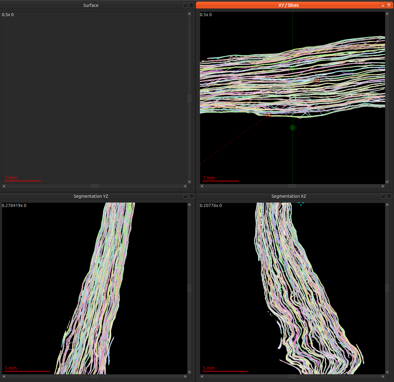
Let this expansion mode run until your volume is densely seeded. It should look like this :
Running a trace
To run a trace, simply right click an existing segmentation, and from the context menu select Run trace , you can keep the default settings for now, but they are available in the dialog box if you wish to experiment with them. You can monitor its growth by selecting the traces folder in your volume widget, by clicking on paths on the volume package widget and selecting traces
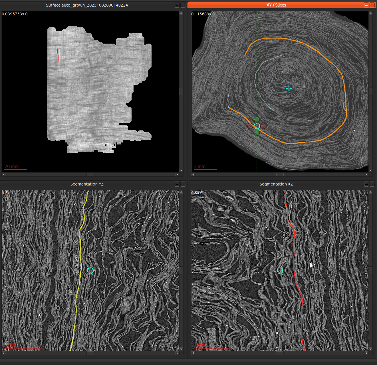
The tracer will run for an indeterminate amount of time , until it runs out of area in which it can continue to grow. This could be 10cm^2 , or it could be 2800cm^2 -- it completely depends on the surface prediction and patch quality. This is a 53cm^2 segmentation from PHerc0172 which completed in about a minute.
Editing traces
You can edit or continue growth on a trace with any of the methods detailed in growing an existing segmentation , and correct them with any of the methods in correcting errors in a segmentation , do note that these traces will have to have been produced after the recent VC3D changes, as prior ones did not include a generations.tif, which is necessary for that growth method.